Your shopping cart is empty!


Which Power Supply?
Especially for beginners in the anodizing field, there is often uncertainty regarding the selection of the appropriate power supply.
In this article, we provide you with some information on choosing the right power supply for your anodizing process and on correctly setting current and voltage.
Content
1. Types of power supplies
There are a variety of models of the DC power supplies considered here (we leave AC power supplies aside, as we only use direct current for our type of anodizing). Depending on the application, these differ significantly.
-
Unregulated fixed-voltage power supply
With this type, neither voltage nor current can be adjusted, and there is no regulation. This type is not recommended for anodizing. -
Regulated fixed-voltage power supply
Again, no adjustments can be made. A regulated, fixed voltage is supplied. Usually, there is also a current limit and occasionally a display for the flowing current. This type is also not suitable for anodizing. -
Battery charger
Here, voltage adjustments are usually not possible. However, at least the higher-quality devices have current regulation and a setting option. For anodizing, this type is mostly not suitable. In particular, the low output voltage often prevents proper layer formation. Additionally, the fine adjustment of the current (if present at all) often leaves much to be desired. -
Regulated power supply with adjustable voltage
This type of power supply offers options to adjust the output voltage over a wide range (usually starting from 0V). A corresponding voltage display—digital (numeric) or analog (needle instrument)—is practically always present. A current limit typically exists as well. These power supplies are conditionally suitable for anodizing: although no current regulation is available, the values in the bath change very slowly, allowing you to measure the current with a multimeter and adjust the voltage manually every 1–2 minutes. -
Power supply with adjustable and regulated voltage and current (“laboratory power supply”)
Here, all parameters can be set and read. These devices are best suited for anodizing.
Another characteristic in which DC power supplies differ is the type of transformation, i.e., the type of energy transfer from the mains connection side to the output terminals. Broadly, one differentiates:
-
Linearly regulated DC power supplies
These devices have a correspondingly large (and heavy) transformer that steps down the 230V/50Hz AC voltage to smaller voltage levels, which are then rectified and subsequently regulated.
At higher currents, these devices become very heavy because the transformer must be appropriately sized. Pay special attention to continuous full-load capability, as linear regulation generates a lot of heat at low voltages and high currents. -
Switch-mode power supplies (in English “switching power supply”)
Here, the mains voltage is almost always rectified first and then converted into a high-frequency AC voltage (e.g., 150 kHz). Only then does it reach the transformer and is stepped down to the desired output voltage. The major advantage of this type is that, due to the high switching frequency, a significantly smaller, lighter, and therefore cheaper transformer can be used. At the same time, current and voltage can be regulated. As a result, practically all modern high-power power supplies are built this way. Our ELV power supply described further below is also of this type.
2. The appropriate power supply
Choosing the right power supply for anodizing is not difficult. The following points should be met (or checked before purchase):
- Type of power supply: DC power supply
Make sure you only use such power supplies—not AC power supplies. The output terminals should be labeled “plus” and “minus” in some way. - Adjustable voltage range (“How many volts does the device have?”):
- Basically: the higher the maximum output voltage, the better. With a power supply adjustable from 0–50V, you can perform the same anodizing jobs (with otherwise identical data) as with one adjustable from 0–30V, but you have additional reserve for hard anodizing layers.
- The guideline for normal decorative layers (practically 90% of all anodizing) is:
Adjustable voltage range of at least 0–25V - If you also want to produce hard anodizing layers (> 25µm layer thickness), power supplies with voltage ranges of 0–60, 0–90, or even 0–120V may be suitable.
- Choice of current range:
We recommend 1.5A per dm² of anodized surface for decorative layers. For example, if you purchase a power supply with an adjustable range of 0–5A, you can anodize workpieces with a maximum surface area of 5A/1.5A*dm² = 3.3 dm². Important: beginners often underestimate the total surface area of a component. Remember to include all surfaces such as cavities and back sides. Also, experience shows that with success, the demands and component sizes increase—so plan generous reserves for maximum current!
Again: the higher the maximum current, the better (and unfortunately, the more expensive). - Clean regulation across the entire range
To anodize small parts correctly, the current must be adjustable cleanly even at low current levels. Many inexpensive power supplies offer only coarse adjustment or cannot be regulated below a certain minimum. This can cause problems with small single parts.
So: make sure the current regulation works cleanly down to 0 amps. - Continuous full-load capability
Ensure sufficient continuous full-load capability. Often, maximum values are only reached for a limited time (e.g., 5 minutes)—for example, when heat sinks are undersized, causing the device to overheat and shut down. Good devices can deliver their maximum power continuously. - Short-circuit resistance
The power supply should be continuously short-circuit-proof. In the event of accidental contact between the anode and cathode (e.g., when hanging the workpieces), the device must not be damaged.
3. Setting current and voltage
Using a simple device as an example, we will now show you how to correctly set and use your power supply. We are using the SPS-9000 power supply from ELV (an older but quite usable device) with the following specifications:

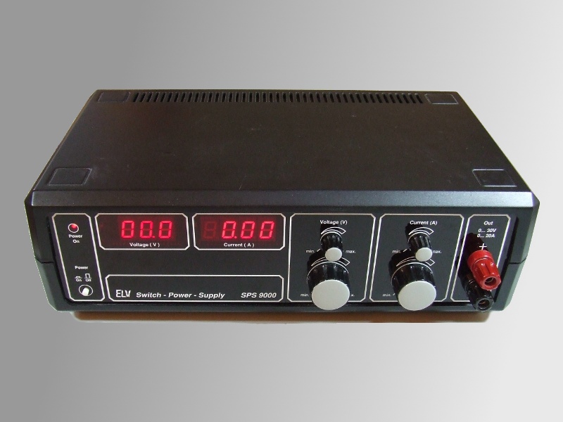
- Design: primary-switched power supply with high efficiency
- Output voltage: 0–30V, regulated, display resolution 0.1V
- Output current: 0–20A, regulated, display resolution 0.01A
- Coarse and fine adjustment for voltage and current
- Full-load and short-circuit resistant
Procedure
- Set all preset values to 0
First, turn both voltage and current fully down to zero. - Short-circuit
Now short the output, i.e., connect the positive and negative terminals. - Turn the voltage up slightly so that current can flow.
- Set the desired current.
- Remove the short circuit — the set voltage will be displayed, the current drops to 0.
- Set the desired maximum voltage.
- Connect the positive and negative terminals to the anode and cathode.